Basic knowledge and multiple applications of magnetic coupling
2025-03-24 08:31Magnetic Coupling (Magnetic Shaft Coupling / Permanent Magnetic Transmission Device)
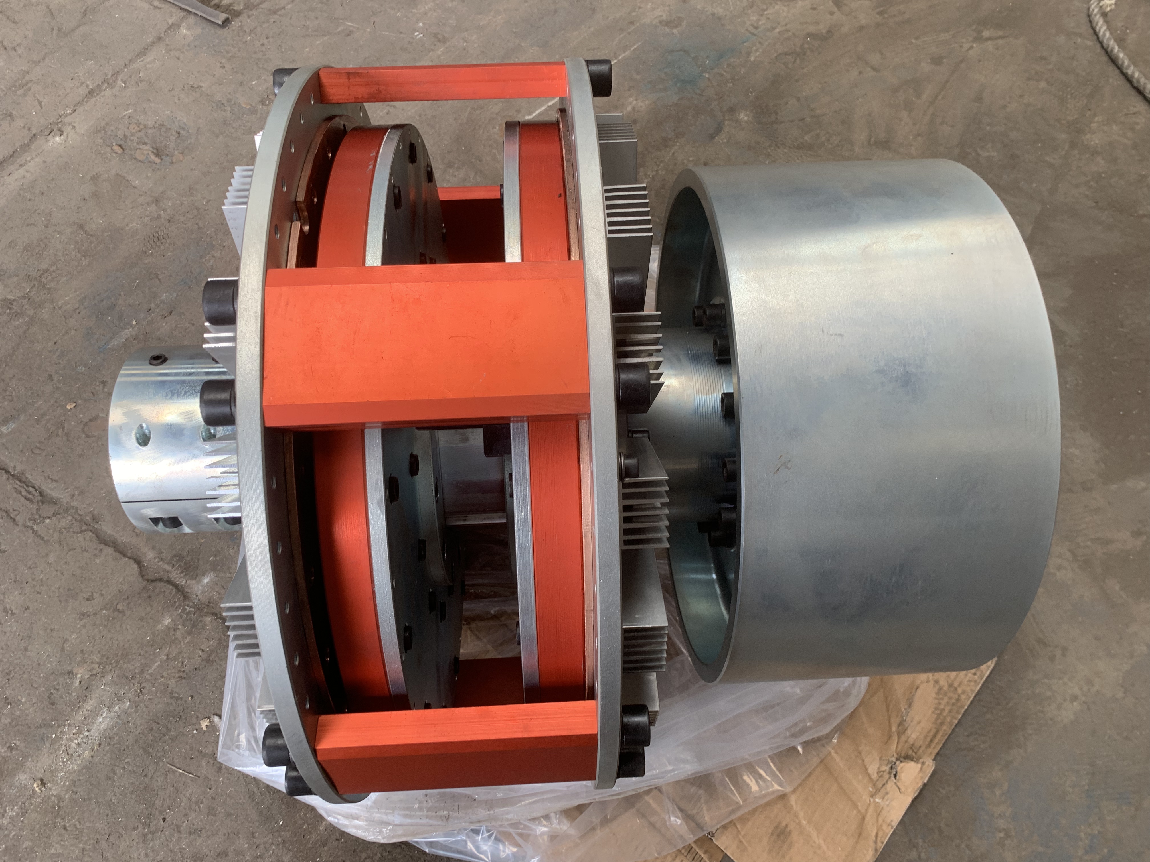
A magnetic coupling, also known as a magnetic shaft coupling or permanent magnetic transmission device, consists of three core components: a copper rotor, a permanent magnet rotor, and a controller. The copper rotor is typically connected to the motor shaft, while the permanent magnet rotor is linked to the driven machine’s shaft. A critical feature is the air gap between the two rotors, which acts as a flexible connection, enabling torque and speed adjustment between the motor and the driven machine. By adjusting the air gap size, magnetic couplings can be categorized into standard, delayed, torque-limiting, and speed-regulating types.
According to GB/T 29026-2008 (Electrotechnical Terminology – Control Motors), a magnetic coupling is defined as a device that transfers torque from a prime mover to a driven apparatus via magnetic forces. It can be classified into synchronous and asynchronous types. Its working principle leverages advancements in transmission technology, material science, and manufacturing processes. In the 21st century, as manufacturing technology evolves, magnetic couplings are not only applied to conventional machinery but also enable equipment operation in extreme environments. Permanent magnet eddy current transmission technology exemplifies this trend, offering energy efficiency, environmental friendliness, and alignment with sustainable development principles.
Internal Structure
The magnetic coupling comprises an outer magnet assembly, inner magnet assembly, and an isolation sleeve.

Both inner and outer magnet assemblies consist of radially magnetized permanent magnets with alternating polarities arranged circumferentially on low-carbon steel rings, forming a magnetic circuit assembly.
The isolation sleeve is made of non-ferromagnetic, high-resistivity materials (e.g., austenitic stainless steel) to ensure magnetic isolation.

Working Principle
At rest, the N-pole of the outer magnet aligns with the S-pole of the inner magnet, resulting in zero torque. When the outer magnet rotates (driven by the motor), friction and resistance initially keep the inner magnet stationary. However, as rotation continues, an angular offset develops in the air gap. This offset generates a pulling force on the inner magnet, causing its N-pole (or S-pole) to rotate. This non-contact torque transmission via magnetic forces is the core mechanism of magnetic couplings.
Key Advantages
1. Non-Contact Transmission
Magnetic couplings transmit power through magnetic coupling instead of physical contact (e.g., gears or bearings), eliminating mechanical wear and significantly extending service life.
2. Noise and Vibration Reduction
The absence of physical contact ensures near-zero noise and vibration during operation. This makes them ideal for noise-sensitive environments such as medical devices and laboratories, while also improving workplace comfort and safety.
3. High Transmission Efficiency
Magnetic couplings minimize energy loss and friction compared to traditional mechanical couplings, enhancing efficiency. They are widely used in industrial production lines, wind turbines, and other high-demand applications.
4. Leakage Prevention
A key design goal of magnetic couplings is to solve leakage issues in fluid transmission. The isolation sleeve fully encloses the inner rotor and driven components, converting dynamic shaft-body seals into static sleeve-body seals. This fundamentally eliminates leakage risks, making them indispensable in applications requiring strict sealing, such as chemical and pharmaceutical industries.
